|
|
|
| |
|
|
Interface
Card
The
Principle Of Operation
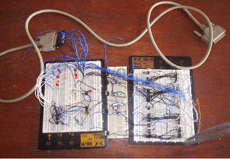
Interface
circuit in test board
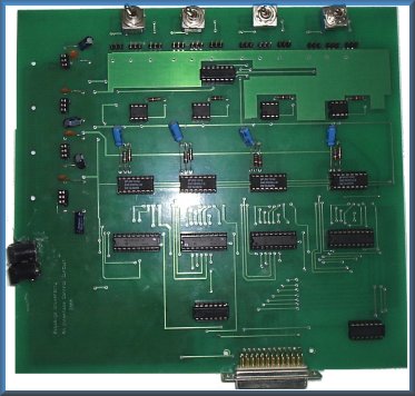
Printed
Circuit Board
- First we start from the
parallel port which is the source of digital data from the
computer to the interface circuit.
We deal with the 8 data lines and the 4 control lines as
we use 8 bit latch and 8 bit DAC for each channel this for
obtaining high resolution.
- The idea for using four
latches for the 4 channels is that we must produce an
output voltage for each channel simultaneously as each
latch has an input enable and an output enable pine and
the 8 input data lines and the 8 output data lines.
- For achieving the output
voltage for each channel we will make a loop that the data
lines output from the parallel port is input to the first
channel which is selected (input enabled) using one
control line but the data don not out by making the out
put enable pin is low because we need output from the 4
latches is at the same time and this operation done at time which the other 3 latches is
disabled to receive data from parallel port by making the
input enable pin is low for them then enable the second
lathe for receiving the 8 data line from parallel port and
disable the others and still channel one do not produce an
output.
- Then enable channel 3 for
receiving the data line and disable the other ,then enable
channel 4 for receiving the data from the parallel port
but in the case the output of the 4 channel will produce
as the output enable pins for the 4 channel is connected
together and connected to the input enable pin of the last
channel receive data from parallel port and so the output
of the 4 latches is produce at the same time then input to
the second section of digital to analog converter used for
each channel that is
8 bit DAC which will convert these digital data to the
corresponding analog current represent it for each channel .
- Then using current to
voltage converter using lf351 OP-AMP which output is then
the analog voltage required for each channel.
- The binary data required for
each channel depending on the measuring voltage required
for each channel is to be controlled using the software
used .
- Enables
the user to manually
or electronically control ( Auto pilot ) the plane
.
- Converts
the plane control from the manual mode into the electronic
one.
- IT
uses the parallel port as an input of data from the base
station.
- Includes
4 Simultaneous Channel For complete control of the RC
plane.
- The
main components used are DACs ,Latches ,Switches
and OP-AMPs.
- High
Resolution for accurate control of the plane.
- Designed
and printed using the most modern technology to ensure
spurious performance .
|
|
|