|
Interface
Card
Generation Of
interface Circuit
Before
we start to design the interface circuit we will begin with a
brief introduction of the
theory of operation of the plane's Radio.
- Plane's
Radio
theory of operation
The
plane's radio is divided into four main sections
- The
input section
- The
encoder section
- The
RF section
- The
antenna section
 the
input section is the most important section that we will deal
with. the
input section is the most important section that we will deal
with.
It supplies the encoder section
with the voltage requirements of each Radio Channel.
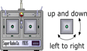
The diagram alongside shows a
basic 4 channel transmitter.
There are
2 sticks, each of which controls 2 of the 4 primary flight
controls.
Each stick is gimbaled so that it can be moved in both axes.
The
up and down movement controls either elevator or throttle, and
the left and right movement
controls either the ailerons or rudder.
The
sticks are sprung so that they return to the center position
when released, with the exception of the throttle control
which has a ratchet mechanism so that it will stay at the
throttle position selected.
Which
stick operates which control is determined by the mode
of the transmitter These
are:
Mode 1 :
 This
has pitch and roll control on separate sticks, with roll
control on the right stick, and pitch control on the left.
The perceived advantage of this layout is the
separation of pitch and roll control onto different sticks,
which is considered to give more precise control over both as
operation of one cannot inadvertently change the other. This
has pitch and roll control on separate sticks, with roll
control on the right stick, and pitch control on the left.
The perceived advantage of this layout is the
separation of pitch and roll control onto different sticks,
which is considered to give more precise control over both as
operation of one cannot inadvertently change the other.
Mode 2 :
 This
has pitch and roll control on the same stick, in a manner
similar to the way the primary controls of an full size
aircraft operate. The
other stick has the yaw and throttle controls. The perceived
advantage is that as pitch and roll are the primary means of
controlling the models flight path, having them on the same
stick makes it easier to co-ordinate the two. This
has pitch and roll control on the same stick, in a manner
similar to the way the primary controls of an full size
aircraft operate. The
other stick has the yaw and throttle controls. The perceived
advantage is that as pitch and roll are the primary means of
controlling the models flight path, having them on the same
stick makes it easier to co-ordinate the two.
Mode 3:
This
control stick configuration has the rudder and elevator being
controlled by the right stick while the left stick controls
the ailerons (roll) and throttle.
§
Voltage
requirements:
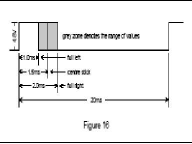
There
is a generally accepted standard for the pulse width range to
ensure inter-operability between the products of various
manufacturers and a typical signal is represented in Figure
16.
The full ± 0.5ms
range of pulse widths is shown although most systems do not
utilizes it all.
Also shown is the pulse repetition rate, or frame rate, of
20ms which means that each channel is updated
50 times per second. A servo, when driven by this
signal, will adopt a position determined by the width of the
pulse with, for example, 1ms representing fully anti-clockwise
and 2ms fully clockwise.

|